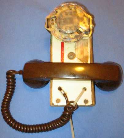
 The phone as it normally sits around. The base is a piece of pressure-treated 2x4
that I hollowed out. Note to self: pressure treated wood is hard to chisel.
The front panel is a bit of fiberboard or somesuch with a shiny front.
The phone as it normally sits around. The base is a piece of pressure-treated 2x4
that I hollowed out. Note to self: pressure treated wood is hard to chisel.
The front panel is a bit of fiberboard or somesuch with a shiny front.
Since it seems such a fad these days to case-mod a computer and then make a
website about it, I thought I'd make a website about my case-moded phone, made
in 1992. Phone parts came from a Western Electric (so said the handset) desk
rotary phone. Inside those old desk phones, there are two breeds that I've seen.
One breed has a small circuit board with lots of slip in spade connectors, four
connections possible per connector. The other breed has a metal and plastic box
with screws on the top for the spades. My phone is based on the circuit board
type. The metal box would not fit within a 2x4. I think the metal box ones are
newer, those are the only ones I've seen with DTMF (Touch Tone to lay folk)
dialing.
The phone as it normally sits around. The base is a piece of pressure-treated 2x4
that I hollowed out. Note to self: pressure treated wood is hard to chisel.
The front panel is a bit of fiberboard or somesuch with a shiny front.
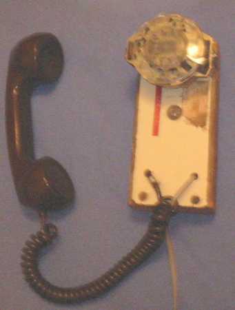 At this point the colors in the pics go all wonky. That doesn't matter though.
This photo is to show that the handset does not activate any on/off hook mechanism.
At this point the colors in the pics go all wonky. That doesn't matter though.
This photo is to show that the handset does not activate any on/off hook mechanism.
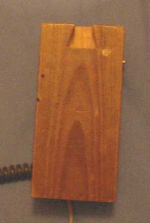 The back of the phone, showing the dovetail I intended to use for a wall hook,
but never built that bit.
The back of the phone, showing the dovetail I intended to use for a wall hook,
but never built that bit.
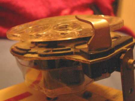 The dial is attached with two L-brackets. The protective plastic on the bottom
is very useful.
The dial is attached with two L-brackets. The protective plastic on the bottom
is very useful.
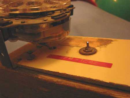 The red sticker has my phone number, circa 1995, on it. The little switch there is
a 3-pole dual-throw switch wired just like the original in the Western Electric phone
I gathered all the parts from.
The red sticker has my phone number, circa 1995, on it. The little switch there is
a 3-pole dual-throw switch wired just like the original in the Western Electric phone
I gathered all the parts from.
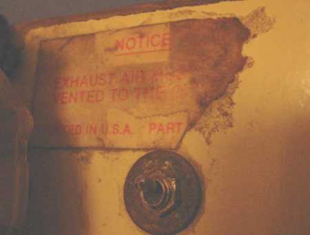 NOTICE
EXHAUST AIR MUST BE
VENTED TO THE OUTSIDE
PRINTED IN U.S.A.
PART ...
I got this label off of a central
vacuum (a vacuum that sits in one place and uses pipes throughout the
building and a long hose).
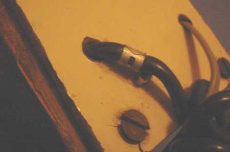 The brown wire goes to the handset. The metal collar has a hook which used to
attach the bottom sheet metal of the phone. Now it attaches to a staple. The
gray wire is a regular phone wire. Originally I wired it up to spade connectors
to attach to the board in the phone, just like the original. With the third
cord, I deciced to install a RJ-11 socket in the phone. Note that the hole in
the front panel is not big enough for a RJ-11 plug. I have to thread the cord
through and then crimp a plug on it. Still much easier than crimping a pair of
spades. (Guess which crimp tool I don't own.)
The brown wire goes to the handset. The metal collar has a hook which used to
attach the bottom sheet metal of the phone. Now it attaches to a staple. The
gray wire is a regular phone wire. Originally I wired it up to spade connectors
to attach to the board in the phone, just like the original. With the third
cord, I deciced to install a RJ-11 socket in the phone. Note that the hole in
the front panel is not big enough for a RJ-11 plug. I have to thread the cord
through and then crimp a plug on it. Still much easier than crimping a pair of
spades. (Guess which crimp tool I don't own.)
 A side view, you can see the hole for the dial wires. Those are still spade
connectors.
A side view, you can see the hole for the dial wires. Those are still spade
connectors.
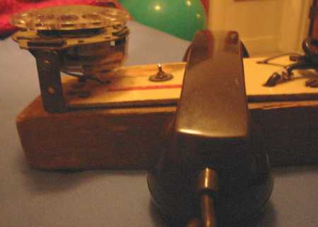
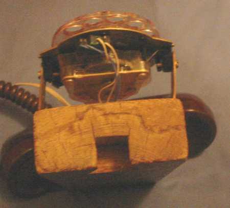 A top view of the phone. Part of the original plan was to hang it from a wall
mounted 2x4. The handset is just the right width to fit comfortably on top of
a 2x4, and would have sat on the top of the wall mount.
A top view of the phone. Part of the original plan was to hang it from a wall
mounted 2x4. The handset is just the right width to fit comfortably on top of
a 2x4, and would have sat on the top of the wall mount.
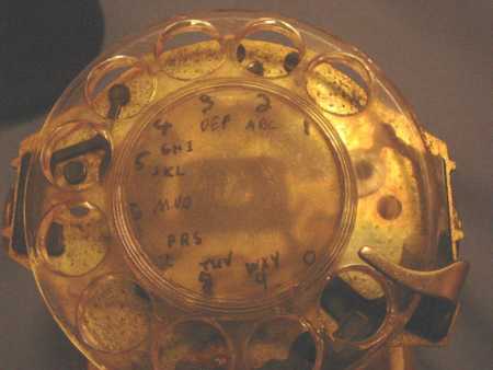 When I originally made it, I had labeled the numbers inside the finger holes,
but later I decided that labeling the center of the dial worked better. The
numbering was done in india ink with a dip pen, then painted over with
glow-in-the-dark acrylic medium (hence the lack of shine in the center). You
can just make out the very small hole between 9 and 0 that is used to take the
dial off. Using the phone without the plastic dial, or without the finger
stop is difficult. I've tried.
When I originally made it, I had labeled the numbers inside the finger holes,
but later I decided that labeling the center of the dial worked better. The
numbering was done in india ink with a dip pen, then painted over with
glow-in-the-dark acrylic medium (hence the lack of shine in the center). You
can just make out the very small hole between 9 and 0 that is used to take the
dial off. Using the phone without the plastic dial, or without the finger
stop is difficult. I've tried.